This chapter provides an overview of the application’s modeling interface. Figure 1 shows an overview of the modeling interface. The areas labeled with numbers are explained in more detail below.
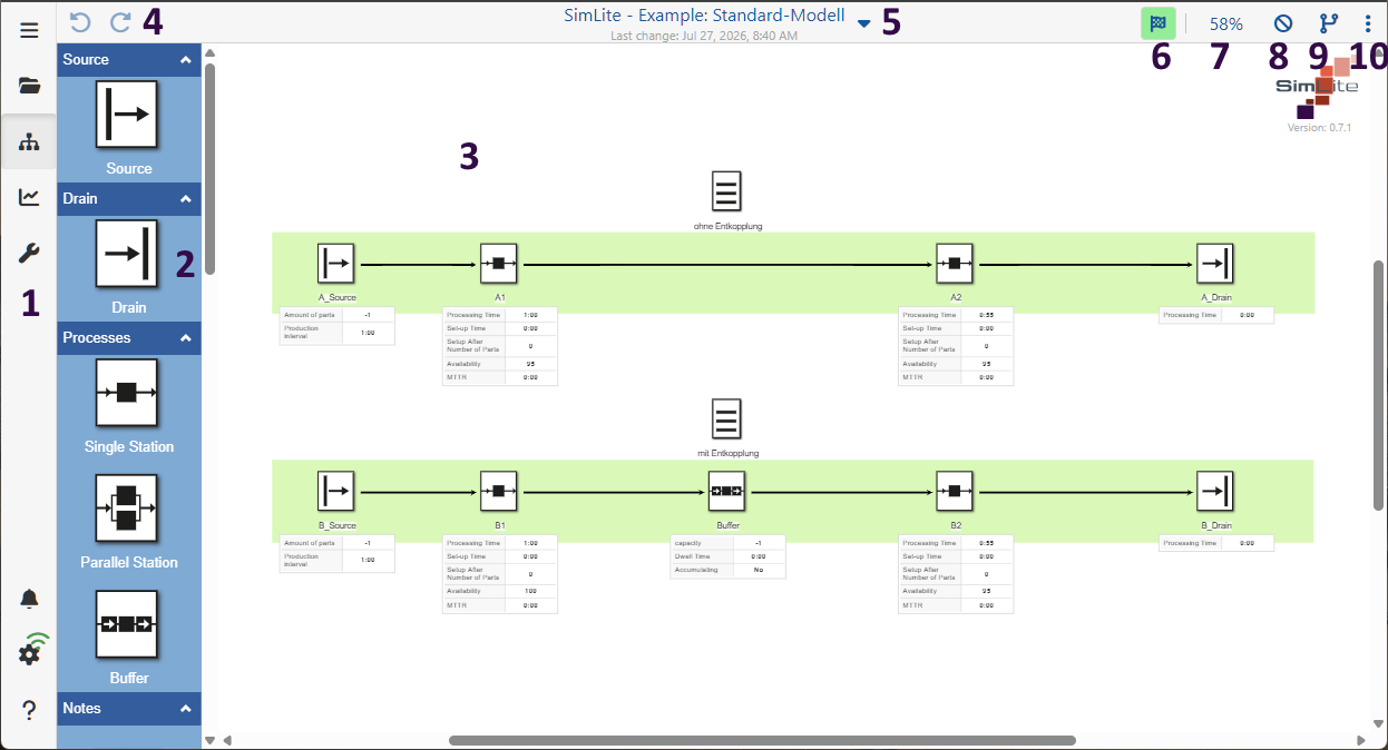
Figure 1 - Modeling Interface

The menu is located on the left side of the application. For details on the menu, see the chapter Menu Bar.

The toolbox may contain various objects depending on the connected model. Objects can be dragged from the toolbox to the right onto the modeling interface using drag-and-drop to create a model.
For more information on working with objects, see the chapter Using Objects.

The largest area of the application is dedicated to modeling. Here, you can create and manage models. Instructions can be found in the chapter Using Objects.
You can zoom in or out on the modeling interface by holding down the [CTRL] key and rotating the mouse wheel.
In the tablet or Smartphone version, this function can be accessed using the standard zoom gesture.

These two buttons allow you to undo or redo actions that have already been performed, such as inserting objects. Changes to parameter settings are not affected by this.

The name of the currently selected project and the currently selected alternative is displayed here (“Project Name”: “Alternative Name”).
Below that, the time of the last change in the modeling interface is always displayed. Clicking the arrow icon opens a menu where you can configure various settings for the current project.
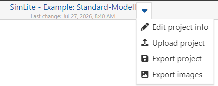
Figure 2 - Top Menu Bar
Edit project info opens a dialog box where you can change the project’s name and description.
Upload project uploads the project to the server (with a prompt asking who the project should be shared with).
Export project opens a dialog box where you can specify the export settings before exporting the project as a *.simlite file.
Export images opens a dialog box where you can export the project’s images.
In this dialog box, you can choose whether to export images from specific alternatives or from all alternatives. The result is a *.zip file named after the respective project.

The icon displays the current status of the simulation for the currently selected alternative. Clicking the icon starts a (new) simulation. Depending on the status, the icon can take on the following forms:
|
Simulation results available
|
|
Alternative is currently being simulated
|
|
No simulation results available
|


Clicking the percentage value allows you to adjust various zoom settings.
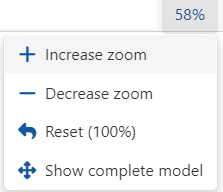
Figure 3 - Zoom

This button allows you to hide selected elements from the drop-down list in the modeling interface.

Figure 4 - Hide Elements

Clicking the button |
|
opens the Alternatives sidebar, where alternatives can be created and managed. For details, see the chapter Create and organize Alternatives. |


Clicking the button |
|
opens a drop-down menu with various settings for the modeling interface, which are explained below. |

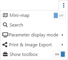
Figure 5 - Modeling Interface Settings
Mini map
This button allows you to show or hide an overview window, which helps you maintain an overview of the entire model, especially in larger projects.
Search
Clicking the magnifying glass icon allows you to search for objects via a dialog box.
The figure below shows the dialog box with the drop-down menu open, which contains all objects used on the modeling interface.
Once an element is selected and the search is started using the Search button, the corresponding element is selected on the modeling interface and the view is centered on that object.
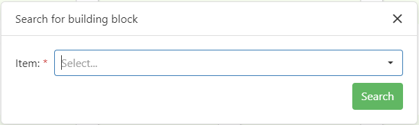
Figure 6 - Search
Parameter display mode
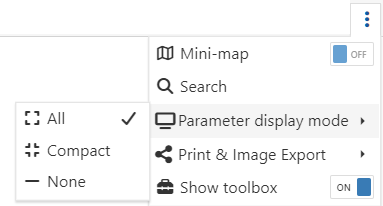
Figure 7 - Parameter Display Mode
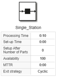
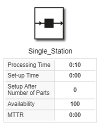
Figures 8 through 10 show an example of a parameter view.
Figure 8 - All Parameters |
Figure 9 - Compact Parameters |
Figure 10 - No Parameters |
Print and Image Export
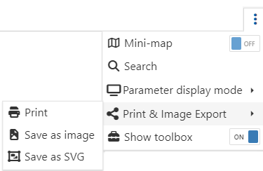
Figure 11 - Print and Image Export
Save as image/SVG
To export as an image (*.png) or as an SVG, simply select the corresponding option from the drop-down list. Windows Explorer will then open, and you can save the file.
Clicking Print opens the print preview. The print settings can be found in the side menu. Here, you can also print the current alternative directly as a PDF.
It is also possible to have the system automatically calculate the width of the PDF to be generated based on the aspect ratio of the model by checking the Dynamic Width check box.
The button at the end of the side menu opens the system printer settings. Use the Print button to print the selected alternative. Use the Cancel button to return to the previous view.
Show toolbox
This slider can be used to show or hide the toolbox.
© SimPlan AG - Hanau District Court, Commercial Register (Part B) 6845 - info@simplan.de - www.simplan.de/en