This chapter describes and explains the global application settings. These settings are project-independent and are therefore available at all times, regardless of the user’s login or whether a project is open.
Contents
2.2 Default Routing for new links
2.4 Initial parameter display mode
2.7 Confirm reverting parameters to main alternative values
2.8 Avoid exact overlapping of nodes
2.10 Label location for link sequence
 Language (DE/EN)
To change the language, simply select the desired language from the drop-down menu. The setting is applied automatically.
Changing the language adapts not only SimLite’s dialogue prompts but also the attributes of the objects to the selected language. Static and dynamic metrics are also displayed in the desired language.
 Server URL
The status of the server connection is displayed in the Server URL line. To edit the URL, simply click Edit at the end of the line.
 Return License
The Return License button allows the user to disconnect from the server. This returns the view to the login screen, as described in the Login Window section.
Information on the license currently in use (type, validity) is also displayed.
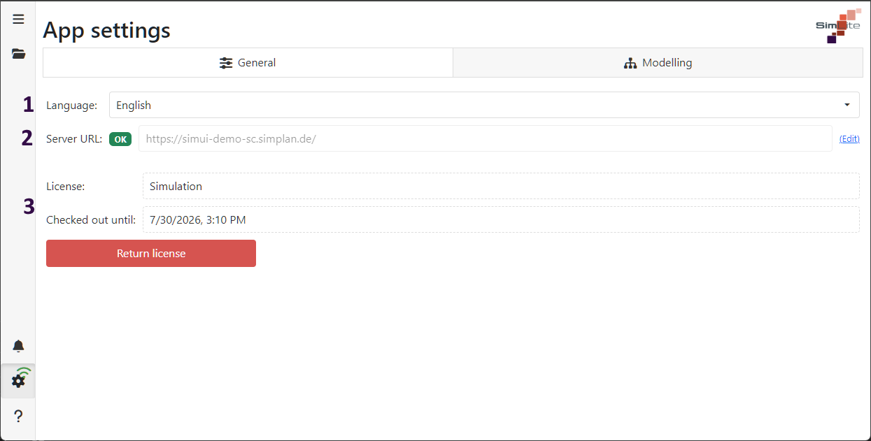
Figure 1 – General Settings
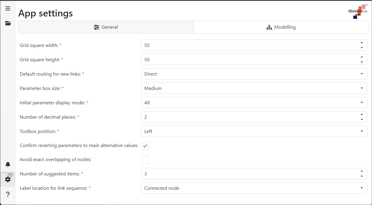
Figure 2 – Settings Overview
The Grid Square Width and Grid Square Height options can be used to set the size of the grid in the modeling area (see Figure 2). The grid can be enabled or disabled in the project settings (local).

Figure 3 – Grid Squares
2.2 Default Routing for new Links
The Default Routing for new Links setting allows you to define how connections between objects are displayed.

Figure 4 – Default Routing
In the Parameter Box Size setting, you can choose between two sizes for displaying the parameter boxes in the modeling area.

Figure 4 – Parameter Box Size
2.4 Initial Parameter Display mode
This setting allows you to specify which parameter display should be set as the default (see the chapter Overview Modeling surface, Figures 8–10).

Figure 5 – Parameter Display
Here you can specify the number of decimal places. This setting applies to all parameter displays and all static metrics.

Figure 6 – Number of decimal Places
This setting determines where the toolbox should be displayed on the modeling interface.

Figure 7 – Toolbox Position
2.7 Confirm reverting parameters to main alternative values
If this tick box is ticked, a dialogue box appears in which the user can accept or reject the resetting of values to those of the reference alternative.
2.8 Avoid exact overlapping of nodes
If this option is selected, objects in the modeling interface cannot overlap exactly.
This option allows you to specify how many objects the algorithm should suggest for further modeling. Details on this function can be found in the chapter Using Objects.

Figure 8 – Number of suggestions
2.10 Label location for link sequence
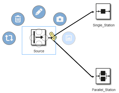
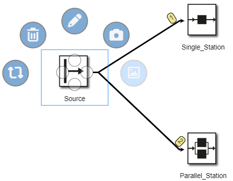
Set the position of the link label to the main node or the linked node.

Figure 9 – Link label position
Figure 10 – Main node |
Figure 11 – Connected node |
© SimPlan AG - Hanau District Court, Commercial Register (Part B) 6845 - info@simplan.de - www.simplan.de/en